
 By Derrell Poole
We sometimes forget our model locomotives are as much machinery as they are scale representations of the prototype; perhaps more so. A scale model may be closely detailed, if not superficially true, to the full-size machine, but it is always a compromise for the miniaturized machine to acquire the performance we expect from it. The laws of physics govern all machines, in accordance to their complexity and any compromise to those laws can result in poor performance or even outright failure. Scale models are facsimiles, while machines are machines – from a simple wheelbarrow to a modern aircraft carrier.
We have latitude and creativity to overcome inadvertent discrepancies that may creep into our static models. In fact, there is nothing a little discretionary weathering can’t fix! But if you build a machine, you will quickly find that no amount of weathering will fix an infraction of the laws of physics.

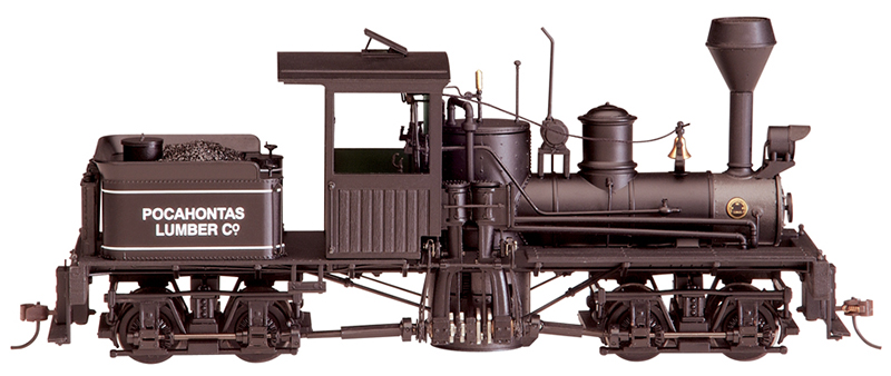
(Fig. 2) The bevel gears have been traded out this beautiful scale model, expelling it from the pigpen and into the realm of a truly marvelous machine. It is indeed a machine first and scale model second. Follow along and we’ll show you how to turn your little pig into a precision machine.
The laws of physics scale just fine, but they often involve mass in the equation, and mass does not scale well at all. Our models contain much less mass and are therefore less affected by the force of gravity, centrifugal force and inertia. For example, if you turned a brass rod to the proportions of a 1:48 scale bell, it might look like an O version of the full size bell but it would not act like one. It would not have the weight or ability to produce even a “scaled down” version of the sound and motion of a real bell. I have never heard an O scale bell actually ring (and I have tried). This lack of mass means while certain concessions can be built into our models in an attempt to make them appear like the full-sized machines, actually making those machines act like the prototype are subject to very tight and rather unforgiving tolerances. The very thing that gives a model a successful appearance as a miniature locomotive, can make it a failure as a miniature machine!

(Fig. 3) NWSL offers 4 kits to repower or modify Bachmann small-scale geared locomotives. The kit we will need for this project is 2801-6 seen on the lower left of the photo.
I think many of us are intimidated by the idea of tearing apart an exquisitely crafted scale locomotive because it seems so complicated (and might have cost a lot of money). The idea of scale is, in fact, all in our heads. The simple reality is that we are actually just playing with little machines. They are not “pretend” little machines; they actually are machines. They work to the principles of mechanics. They have moving parts. They are subject to friction. They are subject to wear. And they are subject to breaking after some degree of normal running. The idea of scale adds some degree of intimidation to our outlook but if we can set aside the concepts of model, scale, and cost, perhaps our perception of a broken machine can reach a less stressful and more pragmatic level. Someone put this little machine together; most likely someone – me or you– can take it apart and put it back together again.
That being said, the Bachmann On30, two-truck Shay is indeed a beautiful, well-executed, scale model. It is also a nice machine with one succinct exception; it often doesn’t run properly. Specifically, there are four bevel gears, two in each truck that have the disappointing tendency to split. At best, split gears spoil slow speed operations and as we all know the trademark of all sidewinders is a very slow and steady operation (See Fig. 2).

(Fig. 4) Read the instructions and examine your model to become familiar with its parts and how they go together. In this photo the universal held in the tweezers is from an HO scale two truck Climax.
Here again, to those who may yet be doubtful, the fact that a model locomotive is a machine first and then to whatever extent a scale model becomes self-evident. You can live with a poor looking model if it runs like a Swiss watch. But the most beautiful scale locomotive is just about worthless to most of us if it doesn’t work. I’ve had plenty of those kinds of models and I know exactly how that feels. I’ve been paid a lot of money to work on some of the most beautiful scale models, which were truthfully little pigs, so far as machinery goes. As long as your fabulously detailed and tasty On30 Shay doesn’t work it is, indeed, one of those little pigs!
Split gears is nothing new in model railroading, and many, many models over the years have had this issue. If you are interested, I have written a sidebar to explain some of the factors that cause model gears to sometimes fail. Certainly, I’m not looking to beat up on Bachmann as they have made a whole lot of great On30 locomotives and to their credit, they do offer replacements gears to the locos that seem prone to gear splitting. But if you have one of the little pigs and need to repair the locomotive, wouldn’t it be nice to have the peace of mind that comes from making a permanent repair that keeps that beautiful Shay running for years to come?

(Fig. 5) The trucks come off very simply by removing the bolster screw. Note the small tray used to hold the parts. One way or another, do not let any parts get away from you as replacements may or may not be available.
Fortunately, there are gears available from our friends at NorthWest Shortline for the Shays. You can order a gear kit directly from NWSL on their website or through your local dealer. Order part number 2801-6. The cost of the kit, which contains the 4 steel bevel gears and an informative, entertaining set of instructions, is $24.95 plus shipping. By the way, NWSL offers kits for other Bachmann geared locomotives and even a kit to re-gauge the HO scale 3 truck Shay to 3-foot gauge. (See Fig. 3)
You should now have your gear kit and your little pig together on your workbench. Follow along as I take you step-by-step and show you how to turn your little pig into a precision machine If this is the first time you’ve done something like this please follow along. If you are an old hand at this sort of thing you can probably follow the instructions in the kit and replace the gears. However you may find a few tips in our discussion that could be helpful.

(Fig. 6) Be careful of the bronze pick up wires on top of the truck bolster. If they are bent and do not make contact with the pads your engine may not run once you’ve put it back together.
First, as with every project, learn as much as you can before you begin. A good place to start is with the instructions included with the kit. Read through these as you examine your machine to help familiarize yourself with all of the parts involved. Likewise, read through the steps I’ve provided here. While the instructions are very well done there is a limit to how much they can say. I have tried to point out in more detail ways to meet some of the challenges you may encounter and to advise you on what you might expect in each step. (See Fig. 4)
As you examine your model take note of how it is put together, where parts are located and how they are oriented to each other. You will see right away that the bevel gears are all ahead of the wheel gears they mate with on both trucks. Note also the locations of the plastic retainers on the drives shafts of each truck. Dave Rygmyr of NWSL warns in the instructions to avoid moving the spacers at all. This is good advice since these spacers directly control the precision location of the gears – especially the trailing or rear bevel gear on the shaft. The precise relationship of these gears to the wheel gears is not a matter of opinion! It does no harm whatsoever to take a pair of calipers and measure the location of this spacer down to the .001″ place. Record this number and how you referenced it to the shaft for each truck, just in case.

(Fig. 7) The rear truck showing the fixed location of the plastic spacer, which the kit instructions warn not to move. This spacer governs the location of both bevel gears on the drive shaft as well as the clearance between each and their mating wheel gears.
One suggestion that is helpful when any project involves complex assemblies is to simply take photos before disassembly. This becomes a fairly sure-fire record of how something is supposed to go together so take the best photos that you can. Today’s digital cameras and cell phones are a very convenient tool to assure proper assembly.
Another suggestion in this particular case is to do one truck at a time. Leave one truck in place and untouched while you make the changes to the other. Remember that both sets of bevel gears lead their wheel gears, front or rear truck, so the only real difference between the trucks is that the drive shafts are at opposite ends of the truck shafts to each other.
This job is really very simple in that we do not have to open the engine itself. All of our work will take place on the trucks and they are easily removed with a screwdriver. Remove the bolster screw and the truck. The drive shaft universals will fall off of the main drive.

(Fig. 8) We disassemble the drive shaft on each truck by first removing the universal – from the front truck in this case. It is better to do this while the shaft is still held in the truck side frame since these are very delicate parts.
As you disassemble the truck put the parts in a small box or container so that you don’t loose them. I am rather bad about sweeping loose parts off onto the floor when I’m not looking and then spend countless minutes crawling around on the floor intensely reciting my sailor’s dictionary of expletives. You must actually put the parts in the container and keep it well beyond your work. (See Fig. 5)
Take a minute to again examine the truck once you have it free from the engine. You will note two pairs of bronze wires sticking out of the top of the bolster. Try to take care of these wires as they bend fairly easily. These are the contact wires that conduct power from each side of the truck to the motor or DCC decoder. If they get bent so that they do not touch the pick up pads on the body bolsters, the engine will not run well or at all. They are present on both trucks to maximize electrical pick up.
One factor to note about all electric model locomotives; no matter how many hot or conductive wheels it has, only two wheels are ever actually conducting electricity at any given instance. These are the wheels that present the least amount of resistance at any particular moment. It only stands to reason that while only two points are conducting, (one on each side of the engine) the more wheels you have available, the more options the current has to find that path of least resistance. (See Fig. 6 and Fig. 7)

(Fig. 9) Work the point of a No.11 Xacto blade into the gap between the top insert tab of the shaft keeper and the journal box to dislodge the catch on the tab inside the journal box. Use the blade to pry the tab outward, carefully and slowly.
The instructions in the NWSL kit are very good and we will generally adhere to the steps they suggest. Start as the instructions suggest and remove the universal joint from the drive shaft before taking it out of the truck. It is not very difficult to remove the universal but with the shaft still held in place, it is a bit easier to work it off of the shaft with a pair of tweezers or needle nose pliers. These are delicate parts that include a rubber-like ring and they have a tendency to come apart. It isn’t that they are difficult to put back together but like all components of this model, the less you have to do them, the better, since they tend to wear poorly when mistreated. (See Fig. 8)
Next, the instructions describe how to remove the drive shaft from the truck. This operation is perhaps the most tedious of the entire project. The keepers that hold the shaft in place are located in the ends of the axle journal boxes and they are held captive by very fine catches on the ends of the insert tabs. There are two insert tabs, one on the top and one on the bottom of each keeper and they may or may not be glued into place. Since they are acetyl plastic, the glue can easily be worked loose but the true challenge of removing the keepers is to undo the catches locked inside the face of the journal box. I used a No. 11 Xacto blade. Carefully work the blade into the journal box above the top tab using the sharp blade to carefully cut any glue loose without marring the keeper or the journal box. (See Fig. 9, Fig. 10)

(Fig. 10) The keeper may have been glued in place, some are and some are not. Work carefully and slowly and be aware that the keeper can suddenly pop loose and abruptly disappear.
Haste will be to your disadvantage here so take your time and work patiently. Eventually, you will work the tab loose. As you pry it out be aware that these parts can suddenly pop out of place and go off somewhere into oblivion. Once again you will be crawling around on the floor cursing your misfortune. Take care and hold the part securely with a set of good tweezers. You might even consider laying a sizable piece of clear plastic film over the operation. I’ve tried this with other projects and the disadvantage may be less clear visibility of the work, but in order to foil any undesirable trajectory, it may save you some grief. (See Fig. 11)
Once you have the keepers out of the way and the shaft removed from the truck, check to make sure there is no debris – in particular glue if it was used – inside the journal box. As the instructions state unless all of the glue is removed it will cause trouble when the keepers are reinserted. Use the point of the knife to work all of the glue out from the corners and niches. (Fig. 12)

(Fig. 11) With both keepers out and the shaft removed take the time to clean the inside of the journal boxes. Left over glue residue will cause trouble when replacing the keepers.
Next, remove the old bevel gears from the drive shaft. These should be easy to pull off with your fingers even if they are not split. In creating this article I used two models owned by people from different areas of the country. Two models, eight bevel gears, and eight cracks. Yep, all eight gears were cracked. So it seems highly likely your gears will be cracked – at least some of them. It does makes it very easy to remove them.
We are almost ready to press the new steel gears onto the drive shaft of the first truck. If you are an old hand at pressing delicate shafts into tight steel holes you probably have your own methodical way of doing it. If not, let me again stress that you should take your time and at no point become careless about how much pressure you are applying and how that pressure is affecting the delicate shaft. Study the shaft for a moment and note how it has a central length that is 2mm diameter and at either end it steps down to just 1.5mm in diameter. It stands to reason that the center part is stiffer than the two end parts, so be especially attentive of the ends of the shaft. Nevertheless, the entire shaft is still very delicate and bending it is a very real possibility. (see Fig. 13)

(Fig. 12) Finish disassembling the shaft by removing both of the plastic gears. These should come off easily with your fingers even if they are not cracked.
The instructions with the kit offer a couple of ideas on how to successfully press the gears onto the shaft. One suggestion is to use a large drill press with a piece of drill rod or a flat head nail upside down in the chuck. The drill press will likely have a stable spindle that will not give laterally to the small amount of pressure we will apply to the shaft. But the hazard one faces using the drill press with an upside down drill bit or nail is that the entire length of the drive shaft is exposed to the pressure needed to force the gear into position. And the more length of a shaft under pressure the easier it is to bend it. You do not want to bend this shaft! If you do, you will have to replace it.

(Fig. 13) Note that the base diameter is 2mm while each end has been turned down to 1.5mm. The gears will press onto the smaller diameter of the shaft. At this end of the shaft you will press the gear only to a point where it properly meshes with the wheel gear. At the other end (not shown) press the gear completely to the 2mm shoulder.
If you have a drill press use it but I suggest a few tools that will reinforce at least part of the shaft and reduce the length exposed to pressure. NWSL sells several products that can aid you when pressing shafts into gears. The first is the Aligner (part no. 31-4) with a 2mm hole. Next they also offer pressing bits that are provided with their Sensipress (part no. 50-4). These are lengths of 1/8” drill rod with either smaller diameter extensions to them or holes of various depths and sizes. They may or may not list these separately but they are available and a quick call will aid you in obtaining a set even if you don’t purchase the Sensipress. Finally, perhaps the best option would be to purchase raw Drill Rod (or axle/ shaft) material 1/8” diameter (part no. 2125-4) or larger and make your own press bits. You can make both 1.5mm and 2 mm as well as combinations thereof and to any length and depth you wish. The Drill rods are unhardened soft steel and so long as you drill the holes straight it does not matter if they are exactly concentric to the rod diameter. You need a bit with at least a slip fit 2mm diameter hole.

(Fig. 14) Before pressing the gears onto the shaft reduce your risk of bending it by chamfering the hole in the gear on the side of the gear that the shaft will be pressed into. Use a 3/32” (2.4 mm) or moderately larger drill bit held in a pin vice to accomplish this.
I used a NWSL Sensipress but if you use a drill press simply chuck the bit and place the Aligner on the drill press table. Before pressing the gears chamfer the holes a little with an oversized drill bit. This helps reduce the catch of the edge of the hole and guides the shaft into the gear more squarely. The shaft and gear MUST be square to each other.
Place the bevel gear upside down on the aligner over the 2mm hole. Then with the bit or nail in the chuck, bring the chuck down guiding the shaft into the gear. Make sure the shaft is oriented properly so that once the gear is pressed on it will lead position the wheel gear it mates with. You should be pressing the shaft into the back of the rear gear and into the front of the front gear as orient to the front of the locomotive. Take careful consideration of this, as you will find it rather challenging to try and remove this steel gear from that delicate shaft. In fact, it would not be a bad idea to not press the gear at this point but rather undo everything and put it all back together once or twice and double check everything just to be sure.

(Fig. 15) Use a press of some type to carefully press the drive shaft into the steel gears. Make sure the gears are oriented properly.
Once you are confident that the assembly will be correct, start with the rear gear and, carefully, with just enough pressure to move the gear onto the shaft, press it to the shoulder of the 2mm portion of the shaft. If the rear gear is fully seated against the 2mm shoulder of the shaft it should mesh properly with the rear wheel gear with no need for adjustment. If it does not, either it is not fully seated against the shoulder or the spacer on the shaft was moved from its original position. Most likely you will find this gear is correctly in place. If you did move the spacer and you did not record the position of the spacer you will need to adjust it until the gear meshes freely but positively with the wheel gear.
Now place the front gear onto the aligner face up and press the other end of the shaft into this gear. Do not press it all the way to the 2mm shoulder as this gear is to be adjusted into place by trial and error. Leave enough room so that the spacer is on one side of the Journal and the gear falls to the other side. You should now have a completed truck shaft where both gears are facing the same direction – hopefully the right direction. (See Fig. 14, 15, and 16)

(Fig. 16) Once the shaft is assembled you will need to “tune” it to the proper relationship to the wheel gears. Start by laying the shaft in place and spinning the wheels with your thumb as shown. Likely the shaft will pop out of place if the mesh clearance is too tight.
Drop the shaft in the bearings of the journals and thumb the wheel as shown in Fig. 16. Very likely there will be lifting or slight binding of the front bevel gear as it is turned by the wheel gear. This means the gear is too close to the wheel gear. If the gear slips or skips teeth it is too far from the wheel gear. You will need to move the front bevel gear accordingly. The correct position is where both gears mesh solidly yet freely with the wheel gears. I found that approximately .045” clearance between the face of the front bevel gear and the journal box housing (Fig. 17) was a good setting to start with. (See Fig. 17 and Fig. 18)
Once the shaft more or less stays in the bearings as you thumb the wheels remove the shaft and press the universal back onto the proper end. Put a tiny drop of oil on each bearing for the shaft and a small drop on the end of each wheel axle inside the journal boxes. (See Fig. 19)

(Fig. 17) The front bevel gear of each truck must be adjusted. Using a puller tool and a vee plate, adjust the gear in minute amounts to widen the mesh so that it is smooth and does not lift out of place when you “thumb” the wheels. The clearance between the gear face and the journal box should be around .045″ give or take.
Put the shaft and gear assembly back in the bearing seats and press the shaft keepers back into place. If the cavities are clean of debris and old glue this should be a snap – literally. If not you may need to inspect and clean them further. Work at it until the retainers fit perfectly. Once they are seated properly spin the shaft and observe that the wheels turns freely. If they do, not examine the mechanism to try and identify the catch or bind. In most cases the front bevel gear is the culprit and still too close to the wheel gear. With care and a pair of needle nose pliers you can adjust this gear in minute amounts while it is in place until the wheels spin freely without taking the retainers out. Be patient and determined. (See Fig. 20) Once you are happy with the assembly use a no.11 blade with a tiny drop of ACC glue on it to fix the keepers in place. (See Fig. 21 and Fig. 22)

(Fig. 18) Press the universal joint back onto the shaft before reassembling the truck.
You are now ready to mount the truck back onto the bolster of the engine. Before you do check the pickup wires that they will contact the pads on the bolster properly. I like to place a drop of Aerocar “Contactalube” on the pads before I install the truck. (Fig. 23)
Having done the first truck repeat the process with the other. Do everything just described and within a few minutes you should have both trucks running properly and mounted. Place a few tiny drops of oil on the working parts of the machine and then place it on the track. Off you go and have fun! (Fig. 24 and Fig. 25)
Why Gears Fail
Perhaps it would be helpful to understand why these gears, as well as so many others on the market today, have this same problem. In case you haven’t already guessed, it falls back to physics, and in particular it goes directly to the physical properties of the material the gears are made out of, how they are made, and how they are applied to these little machines. Let me say right here that I am not passing judgment on any manufacturer. I am simply observing what has been seen since the beginning of small-scale molded gears.

(Fig. 19) Before you reassemble the truck put a tiny drop of oil in the bearings of the journals and the shaft bearings.
The bevel gears in nearly all of Bachmann’s On3o and HO geared locomotives are made of engineering plastic. There is nothing wrong with plastic gears in themselves. This particular type appears to be a slippery acetyl resin. We often call it by the brand name, Delrin®, even though that brand is not commonly used in model trains. But it doesn’t matter what kind of plastic it is; when processed, all plastics, over time, shrink to some degree. These gears were mold injected, which means the plastic was heated to the point of melting and then hydraulically slammed into the cavity of a diecut mold. Manufacturers like to use cast gears because they are far cheaper to mass-produce than to machine each piece. They also run more smoothly out of the box than some metal gears as they don’t require “run-in” and they are also slightly more tolerant of gear mis-alignment.

(Fig. 20) Once the keepers that hold the shaft are back in place and you are satisfied with the action of the mechanism use the tip of a No. 11 blade to put a tiny amount of ACC on the tab and journal cavity to fix it in place.
But because the plastic is forced by heat to change state from solid to liquid and then back again, the material will shrink over time. This is referred to as “seasoning” in the industry. The vast majority of that shrinkage occurs within hours of molding, but it can take months or even years to completely stabilize.
The gears were cast with a center hole that is, in theory, the correct diameter required to fit onto a steel drive shaft. If this diameter was engineered properly, the gear would shrink to fit the shaft with a relatively strong grip. If it was not engineered properly, if that hole was initially too small to account for shrinkage, at some point the gear will likely split on that unyielding steel shaft. Obviously, a manufacturer is going to tend towards tight, as a hole too large would simply allow the gear to spin on the shaft, rendering the model unable to move.
(Fig. 19) Before you reassemble the truck put a tiny drop of oil in the bearings of the journals and the shaft bearings.
Of course, even if the plastic is engineered perfectly and the shrink is accounted for, but the steel shaft is ever so slightly out-of-spec, you can have the same splitting issue. I have no knowledge particular to the engineering practices of the manufacturer of our On30 Shays but it would seem possible that the shrinkage factor of the material the gears were made out of was not properly considered. Of course, it also might be a simple as these are really tiny scale gears and like all small parts, might be slightly more prone to failure than a bigger part.
There are also factors that are beyond the ability of a manufacturer to control. If you like to weight your cars with depleted uranium and run the locomotives up 8% grades, that is going to put a great deal of stress on the little gears. And if the locomotives are stored in a train room subject to extreme swings in temperature, common sense tells us that plastic and metal expand and contract a different rates and could cause or accelerate failure.
Derrell Poole is the owner of 7th Street Shops, a company located in Hamilton, Mont., specializing in painting, custom building, DCC installation and repair of brass locomotives. He has consulted with a number of firms in the industry including NorthWest Short Line.

(Fig. 21) Test the new gears by spinning the shaft and watching the wheels go. This is a point of either great satisfaction or the realization you need to adjust the front gear a little bit more. With care and a pair of needle nose pliers you can move this gear tiny amounts to adjust it.

(Fig. 22) Use a little Areocar “Connectalube” on the bolster pads to increase conductivity and lubricate the pads.

(Fig. 23) Make sure the truck pickups make contact with the bolster pads to assure conductivity.

(Fig. 24) Once both trucks are completed take a moment to lubricate the moving parts of the engine. Then enjoy a little machine that should serve you for many years to come.

(Fig. 25) Most of the tools used for this project. Left to right; NWSL Sensipress 50-4, a NWSL 2mm Alignment tool (disk) 31-4, a NWSL pressing tool with 2mm hole (call for details), a NWSL vee plate and Puller II 55-4, cyanoacrylate glue, Aerocar “Connectalube,” Aerocar “Heavy oil,” pinvise and drill bit, Phillips bit screwdriver, Xacto knife with No. 11 blade, tweezers, and needle nose pliers.